Long-Distance Microtunnelling: IJS, Jacking Force and Slurry Control
A long-distance microtunnel is not simply a conventional pipe-jacking drive with more pipes behind the machine. As distance increases, jacking force, lubrication, slurry hydraulics, guidance, joint loading, IJS strategy, ground behaviour and operational discipline become one interconnected control system.
Abstract
Long-distance microtunnelling is a systems engineering problem in which thrust, pipe and joint capacity, annular lubrication, face support, spoil transport, separation, navigation, groundwater and operational constraints must remain within a controlled operating envelope. This article presents a project-independent engineering framework based on international standards, peer-reviewed research and manufacturer technical information.
Verification note. No engineering article can guarantee universal correctness for every project. Actual design must follow current approved drawings, geotechnical investigation, project specifications, pipe-manufacturer calculations, MTBM technical data and approved method statements.
01 What Long-Distance Microtunnelling Actually Means
Microtunnelling is a remotely controlled, guided trenchless pipeline installation process in which an MTBM excavates while a jacking system advances the machine and pipe string from a launch shaft. ASCE/CI 36-15 identifies remote control, guidance, jacking thrust and continuous face support capable of balancing groundwater and earth pressure as fundamental characteristics. BS EN 12889:2022 provides the broader European framework for trenchless construction and testing using prefabricated pipes and joints. There is no single universal distance at which a drive automatically becomes long-distance; its engineering significance depends on diameter, ground, groundwater, alignment, allowable pipe and joint loads, lubrication efficiency, thrust reaction, slurry hydraulics, guidance and operating constraints.
02 A Long Drive Is a System, Not a Machine
Machine capacity is essential, but it is only one part of the system. The MTBM and cutterhead, face-support circuit, slurry transport, separation plant, main jacking station, pipes and joints, annular lubrication, IJSs, navigation, survey control, shafts, instrumentation and procedures must operate as one integrated process.
03 Jacking Force: The Central Mechanical Constraint
Required force can be separated conceptually into face resistance and resistance along the pipe string: Ftotal ≈ Fface + Fskin. For an ideal circular pipe, friction relates to outside circumference, drive length and unit interface resistance: Fskin ∝ π · D · L · τ. In practice, interface resistance changes with ground, stress state, lubrication, annular condition, groundwater and pipe–ground contact.
04 Required and Allowable Jacking Force Are Different Questions
Design must determine both the force probably required to move the string and the force that may safely pass through the pipes and joints. Eccentric loading, angular deviation, planned curvature, manufacturing tolerance and joint pressure-transfer materials can reduce allowable longitudinal force. The operating force must remain below the lowest relevant pipe, joint, jacking-station, thrust-structure, IJS or project limit.
05 Why Jacking Force Becomes More Critical with Distance
As more pipe is installed, the contact area exposed to friction increases. Force should not be expected to rise smoothly or linearly: lubrication loss, ground closure, stoppage and restart, curvature, steering corrections and local contact can create gradient changes and peaks.
06 Intermediate Jacking Stations (IJS)
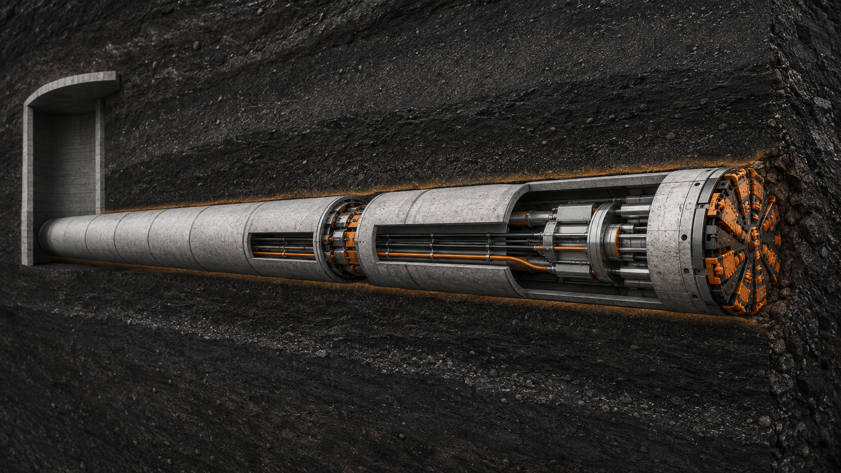
An IJS divides a long pipe string into independently movable sections. Hydraulic jacks advance the section ahead while reacting toward the rear; the main station then advances the rear section and closes the IJS. The sequence distributes thrust rather than requiring the main station to overcome total string resistance in one action. An IJS does not remove friction; it changes how force is transmitted through the pipeline.
07 When Should an IJS Be Installed?
There is no responsible universal rule such as “every drive longer than X metres requires an IJS.” The decision should consider predicted friction and uncertainty, pipe and joint capacity, thrust-wall and main-jack capacity, alignment, geology, groundwater, lubrication, duration, downtime and restart capability. The correct sequence is: Ground model → Force prediction → Sensitivity → Allowable load → Main thrust → IJS layout → Activation criteria.
08 IJS Capacity Is Not Enough: Location Matters
Placing an IJS somewhere in the drive does not guarantee optimum force distribution. Position, reserve capacity and activation strategy should be planned before launch for normal operation, rising load, restart, abnormal resistance and sectional diagnostic jacking.
09 Jacking Force Is Live Engineering Data
A predicted jacking-force envelope should exist before excavation. Actual readings should be plotted against chainage and compared continuously with the design expectation. Main thrust, IJS status, cutterhead torque, penetration, lubrication, slurry parameters, stoppages and geological changes should be recorded together—not merely to record force, but to understand why it changed.
10 Lubrication: The First Defence Against Skin Friction
The cutter or shield normally creates an annular overcut outside the pipe, into which a suitable lubricant is injected. Bentonite lubrication can significantly reduce friction, especially when fluid loss into the surrounding ground is controlled. Laboratory results must not be generalised as universal field values.
11 Lubrication Volume Alone Does Not Prove Quality
Daily litres alone do not show whether the pipe–soil interface is being maintained. In permeable ground, material may be lost rather than retained around the string. Lubrication should therefore be analysed as location + pressure + volume + ground response + jacking-force response.
12 Face-Support Slurry and Annular Lubrication Are Different Systems
In a slurry-supported MTBM, the slurry circuit supports the excavation face and carries excavated material to the surface separation plant. Lubricant injected around the pipes primarily reduces pipe–ground interface resistance and maintains favourable annular conditions. Both may use bentonite or engineered fluids, but their functions, locations and control objectives are different.
13 The Slurry Circuit Has Two Fundamental Jobs
Excavation slurry provides face support and transports spoil. Pressurised slurry balances earth and groundwater forces; excavated solids travel through the discharge line to the separation plant, and conditioned slurry returns through the feed line: Surface plant → Feed line → Excavation chamber → Discharge line → Separation → Conditioned return. Longer circuits make line losses, pump performance, solids loading, density and separation capacity increasingly important.
14 Face Pressure Must Be Controlled, Not Maximised
Higher slurry pressure is not always safer. Insufficient support may contribute to instability and settlement, while slurry infiltration in coarse or loose ground can complicate effective support. Provide sufficient controlled support within an appropriate pressure window, not simply the maximum pressure the system can produce.
15 Flow, Density and Separation Performance
Feed and discharge flow measurements, combined with density measurements, support real-time assessment of excavated material moving through the circuit. The separation plant is part of excavation. If fluid properties deteriorate or solids cannot be removed effectively, the consequence propagates through the complete hydraulic system.
16 Guidance Becomes a Structural Issue on Long Drives
Navigation must match the alignment geometry and distance. Laser systems suit shorter straight drives, while HydroLevel, gyro or total-station solutions may be selected for longer or curved drives. Curvature, angular deviation, tolerances and joint pressure transfer affect allowable force: Guidance → Steering correction → Joint angle/eccentricity → Allowable-force utilisation.
17 Restarting a Long Pipe String Requires Its Own Strategy
A stationary string may not behave like a continuously moving string. Lubrication can change during downtime and static interface resistance must be overcome during restart. Sectional restart through IJSs can reduce the demand of moving the entire stationary string at once. The approved method should confirm slurry condition, lubrication, IJS readiness and instrumentation, define the restart sequence and compare force response with the pre-stop baseline.
18 A Sudden Force Increase Is a Diagnostic Signal
A sudden thrust increase should not automatically be answered by higher hydraulic pressure. Possible mechanisms include lubrication deterioration, local contact, restart resistance, alignment or joint effects, geological change and face resistance. Use the sequence: Force anomaly → Correlate parameters → Diagnose mechanism → Controlled intervention → Verify response.
19 Integrated Long-Drive Monitoring
Data streams should be correlated, not reviewed independently. Trend main thrust against chainage; IJS pressure, stroke and sectional movement; torque, RPM and penetration; slurry pressure, flow and density; lubrication pressure, volume and location; horizontal and vertical deviation; settlement or heave; and operational events such as pipe number, stoppages and interventions.
20 The Seven Critical Control Loops
Ground control governs face behaviour, overcut, fluid loss and friction. Face control maintains stable excavation. Slurry transport carries spoil reliably. Friction control limits accumulated resistance. Thrust control keeps loads within structural and equipment limits. Alignment control maintains geometry while limiting joint effects. Surface and asset control keeps surrounding structures and utilities within acceptable impact limits. A failure in one loop can migrate into another.
21 Failure Signatures Often Appear Before the Tunnel Stops
Unexplained thrust growth may indicate changing interface resistance; rising torque with reduced penetration may indicate deteriorating excavation conditions; abnormal slurry flow or density may signal circuit change; and increasing correction demand may indicate guidance difficulty. Evaluate simultaneous trends rather than isolated data points. A strong team recognises deterioration while the tunnel is still moving.
22 A Practical Long-Drive Decision Philosophy
Predict → Measure → Compare → Diagnose → Correct → Verify. Predict expected thrust, slurry, lubrication and alignment behaviour. Measure reliable operational data. Compare actual performance with the predicted envelope and previous behaviour. Diagnose whether the change is hydraulic, mechanical, geotechnical, structural, survey-related or operational. Apply a technically justified correction, then verify from subsequent data that it solved the problem.
23 What Must Be Decided Before Launch?
Before launch, the team should know the predicted force range; allowable pipe and joint loads; main-jack and thrust-wall limits; IJS positions, capacities and activation philosophy; lubrication arrangement; expected slurry envelope; separation capacity; navigation and survey architecture; monitoring requirements; and credible contingencies. These decisions should not be made for the first time hundreds of metres into the drive.
24 What IJS Cannot Fix
An IJS cannot indefinitely compensate for uncontrolled ground loss, repair an overloaded joint, correct an unsuitable cutterhead, replace effective lubrication, solve undersized slurry transport or separation, substitute accurate guidance or correct a poor ground model. Its principal purpose is force distribution and sectional movement within a properly engineered jacking system.
25 What a Larger MTBM Cannot Fix
A more powerful cutterhead or jacking station increases available capacity but does not remove the need to control pipe loading, lubrication, face pressure, slurry transport or alignment. The objective is not maximum power; it is sufficient controlled capacity with verified reserve.
26 Operational Discipline Is the Decisive Layer
Long-distance drives concentrate mechanical, hydraulic, geotechnical and survey risks into one continuous operation. Procedures must define normal envelopes, escalation thresholds, communication, data ownership, stoppage response, restart sequence and verification. Discipline converts machine capability into repeatable tunnel performance.
27 Frequently Asked Technical Questions
What is long-distance microtunnelling?
There is no universal length; it is defined by the engineering demands created by thrust, pipe loading, friction, slurry hydraulics, guidance, ground, groundwater and logistics.
Is microtunnelling the same as pipe jacking?
It uses pipe-jacking thrust but is characterised by remotely controlled, guided excavation and controlled face support.
What is an IJS?
It allows sections of a long drive to move independently, reducing the force transferred through the complete string or thrust structure at one time.
Is there a fixed distance for IJS installation?
No. The need is determined by friction prediction, pipe and joint capacity, main thrust, alignment, ground, lubrication, downtime and restart risk.
Why is bentonite used?
It may reduce annular interface resistance; in a slurry circuit it may also support the face and transport spoil. These functions must not be confused.
28 Engineering Position and Conclusion
The defining feature of long-distance microtunnelling is not distance itself but control over accumulating uncertainty. Small inefficiencies grow with chainage: slightly higher friction becomes greater total thrust; weak lubrication becomes higher string resistance; longer slurry lines require tighter hydraulic control; guidance errors become harder to correct; and stoppages become more consequential.
Long-distance microtunnelling is not achieved by jacking harder. It is achieved by controlling resistance before resistance controls the project.
Jacking force must be predicted and interpreted continuously. IJSs must be designed as force-management tools rather than emergency accessories. Annular lubrication must be controlled as an engineered interface system. Face-support slurry must be managed as both a ground-support and transport system. Guidance must protect alignment and joint-loading behaviour. Monitoring must combine thrust, torque, advance, slurry, lubrication and navigation into one decision framework.
References
- American Society of Civil Engineers. Standard Design and Construction Guidelines for Microtunneling, ASCE/CI 36-15.
- British Standards Institution. BS EN 12889:2022: Trenchless Construction and Testing of Drains and Sewers.
- Pipe Jacking Association. An Introduction to Pipe Jacking and Microtunnelling. Pipe Jacking Design Guide.
- Kong, C. et al. Frictional resistance calculation and jacking force prediction of rectangular pipe jacking. Scientific Reports 13, 14992 (2023).
- Reilly, C.C. & Orr, T.L.L. Physical modelling of the effect of lubricants in pipe jacking. TUST 63, 44–53 (2017).
- DWA-A 161: Static Calculation of Jacking Pipes, March 2014; corrected March 2021.
- Röhner, R. & Hoch, A. Calculation of jacking force by new ATV A-161. TUST 25(6), 731–735 (2010).
- Li, C. et al. Numerical simulation for an estimation of the jacking force of ultra-long-distance pipe jacking. TUST 89, 205–221 (2019).
- Duhme, R. et al. Theoretical basis of slurry shield excavation management systems. TUST 57, 211–224 (2016).
- Broere, W. On the face support of microtunnelling TBMs. TUST 46, 12–17 (2015).
- VMT GmbH. TUnIS Navigation MT: Microtunnelling Navigation Systems.
Oğuzhan Ataşalar
Microtunnelling & NDRC Project Manager · Dubai, United Arab Emirates