Deep Microtunnelling Under High Groundwater Pressure
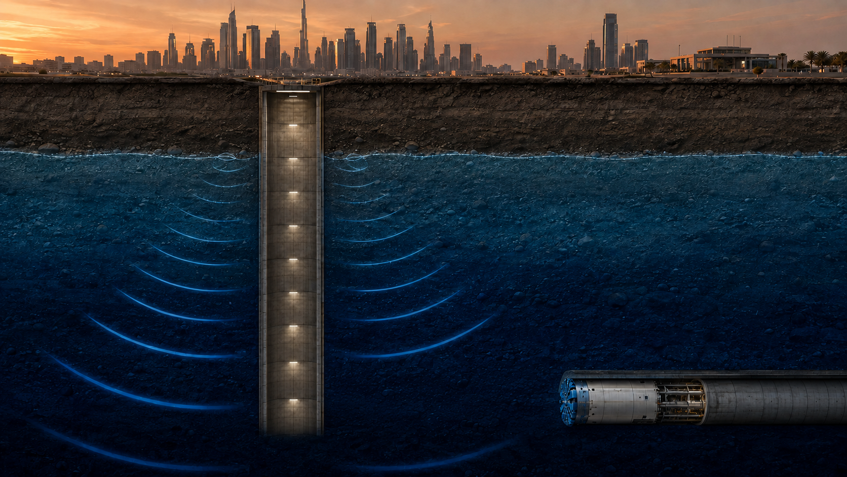
Ground behaviour, face-support control, equipment selection and risk management across different geological conditions
Abstract
Deep microtunnelling below a high piezometric groundwater level is governed not by depth alone, but by the interaction of groundwater pressure, soil permeability, effective stress, face stability, machine pressure rating, shaft watertightness and the ability to maintain control during both advance and stoppage. Insufficient support pressure can cause water inflow, soil loss and settlement; excessive pressure can cause heave, slurry loss or hydraulic fracture.
Safe construction therefore requires a project-specific operating pressure envelope rather than a single universal pressure value. This article reviews the principal design and operational controls for slurry and earth-pressure-balance systems in saturated sand, silt, clay, gravel, mixed ground and fractured rock. It also addresses shafts and portal seals, slurry behaviour, jacking loads, monitoring, planned stoppages and hyperbaric intervention.
Keywords: microtunnelling; pipe jacking; groundwater pressure; slurry shield; face stability; filter cake; deep shaft; hydraulic fracture; hyperbaric intervention.
1. Introduction
Microtunnelling is a remotely operated, guided pipe-jacking method in which excavation and pipe installation proceed from a launch shaft without routine personnel entry at the face. In unstable, water-bearing ground, the excavation face must remain supported throughout advance and during planned or unplanned stoppages. Slurry shields provide this support by maintaining pressurised suspension in the excavation chamber; ITA-AITES identifies this method as particularly suitable for unstable materials exposed to high groundwater pressure or inflow.
The presence of a slurry machine does not by itself make a drive safe. The excavation chamber, main-bearing seals, slurry pumps and lines, valves, separation plant, launch and reception seals, jacking pipes, intermediate jacking stations and emergency power arrangements form one pressure-control system. Failure at any interface can compromise the entire drive.
2. Groundwater pressure and the face-support envelope
For static groundwater, pore-water pressure at a point may be expressed as:
u = γw h
Here, u is pore-water pressure, γw is the unit weight of water and h is the piezometric head above the point. For fresh water, 10 m of head corresponds to approximately 98.1 kPa, or 0.981 bar. This is a hydraulic conversion, not a complete face-pressure design rule. Pressure also varies vertically across the tunnel face; the value at invert level exceeds that at crown level by approximately γw times the tunnel diameter.
The required support pressure must be determined from groundwater pressure, effective soil strength, cover-to-diameter ratio, surcharge, stratification, permeability, tunnel geometry and the selected safety criterion. The lower bound is governed by collapse, soil loss and uncontrolled inflow. The upper bound is governed by blowout, heave, slurry escape and hydraulic fracture.
The objective is not to apply the highest possible pressure. It is to maintain a verified operating window between loss of face stability and pressure-induced ground failure.
3. Ground investigation and hydrogeological model
A deep drive cannot be designed reliably from isolated boreholes and SPT values alone. The investigation must resolve the geological variability that controls excavation, pressure transfer, abrasion and stoppage behaviour. Particular attention is required at old channels, fill/native-ground boundaries, abrupt rockhead changes, faults, highly permeable lenses and interfaces likely to create a mixed face.
- Particle-size distribution, fines content, density, water content and Atterberg limits.
- Effective shear-strength parameters, undrained shear strength where applicable, and SPT/CPT profiles.
- Horizontal and vertical permeability, aquifer boundaries, artesian conditions and time-dependent piezometric levels.
- Cobbles, boulders, rock strength, RQD, discontinuity condition, abrasivity and quartz content.
- Clay mineralogy, adhesion and clogging potential; groundwater chemistry relevant to slurry, seals, concrete and steel.
- Pumping or packer tests where dewatering, fractured rock or high inflow is material to the design.
Tunnel depth must not be used as a substitute for groundwater head. The governing pressure is related to the piezometric surface or pressure level of the relevant aquifer. Multiple aquifers may impose different pressures at the shaft and tunnel horizons.
4. Selection and pressure rating of the excavation system
4.1 Slurry microtunnelling systems
A slurry MTBM balances ground and groundwater at the face through controlled fluid pressure and transports excavated solids hydraulically to a separation plant. The equipment must monitor and continuously balance soil and groundwater pressures and include pressure control, flow measurement, bypass capability and separation suited to the excavated soil.
Slurry systems have a strong application range in saturated granular ground, high groundwater pressure, heterogeneous geology and conditions where uncontrolled inflow is unacceptable. Selection must nevertheless be based on the complete ground model and tested slurry behaviour rather than on groundwater pressure alone.
4.2 Earth-pressure-balance systems
An EPB system uses conditioned excavated material as the face-support medium. It is most effective when the chamber material can be maintained as a plastic, low-permeability plug with controlled extraction through the screw conveyor. Suitability in highly permeable granular ground must be demonstrated rather than assumed.
4.3 System pressure verification
- Excavation chamber and bulkhead; main bearing and seal system.
- Feed, return and bypass lines; pumps, valves, couplings and instrumentation.
- Cutterhead openings, crusher chamber and pressure-sensitive penetrations.
- Launch and reception seals, temporary closures and emergency isolation.
- Air locks and intervention facilities where pressurised access is foreseeable.
A nominal machine pressure rating must not be treated as the permissible continuous operating pressure. Pressure transients, measurement uncertainty, component-specific ratings, wear and the manufacturer's approved operating envelope must be considered.
5. Behaviour in different ground types
5.1 Loose and saturated sand
Loose saturated sand has little or no true cohesion and can flow rapidly when effective stress is reduced. A short pressure loss may initiate water-and-soil inflow, over-excavation and settlement. Control depends on a stable support-pressure envelope, suitable slurry rheology, reliable mass-balance monitoring and immediate investigation of abnormal slurry loss or solids return.
5.2 Silt and low-plasticity soils
Silt may erode or pipe under seepage gradients and can be difficult to separate from carrier slurry. The separation plant must therefore be selected by both hydraulic throughput and separation cut size. Desilters, centrifuges or filter presses may be required.
5.3 Soft, sensitive or adhesive clay
Low permeability can reduce direct water inflow, but adhesive clay may clog cutterhead openings, increase torque, reduce penetration per revolution and accumulate in the chamber or slurry circuit. Water addition alone is not a universal remedy. Anti-clay additives should be selected through compatibility testing.
5.4 Dense or partially cemented sand
Dense and cemented layers can increase cutter loads, torque and abrasion. A sudden transition into loose permeable sand can be more critical than either uniform material. Cutterhead opening ratio, installed torque, crusher capacity, tool wear and pressure-control response must be assessed together.
5.5 Gravel, cobbles and boulders
Coarse open ground may permit deep slurry penetration and substantial losses before a sealing mechanism develops. The MTBM must excavate or crush the anticipated maximum particle size and transport fragments without blocking ports or lines. Slurry formulation, loss-control materials, wear protection and verified crusher capacity are central design issues.
5.6 Fractured rock and mixed face
Massive rock may be stable, while open joints, faults or karstic voids can produce concentrated inflows. Packer testing and pre-excavation grouting may be appropriate. In a mixed face, unequal cutting resistance can cause steering deviation, vibration and preferential excavation of the softer zone.
6. Slurry pressure, infiltration and separation
In fine to medium soils, bentonite may form a low-permeability filter cake at or near the face. In coarser permeable ground, slurry may penetrate the pore network and develop a pressure-transfer zone rather than an idealised thin cake. Excessive penetration can delay effective pressure transfer and raise pore pressure ahead of the face.
Slurry loss must not be answered automatically by increasing pressure. The cause must first be assessed: permeability, open joints or voids, slurry yield stress and filtration behaviour, grading, polymer compatibility and potential hydraulic fracture.
Excavated quantity should be assessed through a corrected solids balance. Feed and return flow alone are insufficient; flow, density and solids concentration, or an equivalent calibrated dry-solids mass balance, should be reconciled with theoretical excavation volume.
7. Shafts, dewatering and portal seals
Launch and reception shafts are pressure interfaces and commonly represent the highest-consequence locations in a deep drive. Checks may include lateral ground and water loading, basal heave, hydraulic uplift, piping, wall-joint leakage, internal bracing, reaction-wall capacity and emergency water-storage and pumping arrangements.
Dewatering must be based on a hydrogeological model and, where appropriate, pumping-test evidence. Drawdown can increase effective stress and induce settlement; recovery after pump failure can rapidly restore uplift and inflow. Monitoring should include shaft water levels, external piezometers and defined standby capacity.
The launch or reception seal must be rated for the design differential pressure and compatible with machine and pipe geometry. Reception readiness - seal, pumps, power, access and emergency response - must be verified before breakthrough.
8. Jacking system, pipes and lubrication
Jacking pipes must resist temporary installation forces and final in-service actions. Design must include axial jacking load, local joint stresses, packing behaviour, permissible angular deflection, external groundwater pressure, handling loads and the manufacturer's declared capacity.
High groundwater does not directly determine jacking force, but it can intensify lubrication loss, soil intrusion into the annulus, long stoppages, deviation and ground movement. The design should establish a jacking-force model, trigger levels, lubrication layout, intermediate jacking-station strategy and restart procedure.
9. Stoppages, restart and loss of power
A stationary pressurised MTBM remains an active geotechnical system. Before a planned stop, face pressure should be stabilised; slurry properties and tank capacity checked; lines managed to limit settlement or blockage; and restart actions agreed.
Critical valves should fail to a demonstrably safe state. Emergency generators, control-system backup, pressure instrumentation and communications should be tested under realistic failure scenarios. The emergency philosophy must define how face support is maintained after loss of grid power, pump control or a primary sensor.
10. Hyperbaric intervention
Where cutter inspection or tool replacement cannot be completed at atmospheric pressure, slurry may be displaced by compressed air while face support is maintained. This is specialist hyperbaric work requiring face-seal preparation, locks, decompression procedures, medical oversight, fire precautions and emergency arrangements.
Applicable legal requirements depend on jurisdiction, pressure and exposure regime. Intervention demand should be assessed during design by comparing anticipated tool life with drive length and geology.
11. Monitoring and observational control
A safe drive uses trends and balances rather than isolated readings. The system should record synchronised chamber pressure, feed and return pressure and flow, slurry density, tank level, cutterhead torque and speed, penetration per revolution, total thrust, intermediate-station loads, line and level, lubrication quantities, shaft water levels and relevant piezometers.
Alarm criteria should consider absolute values and rates of change. A rapid small pressure loss may be more significant than a slow larger change. Surface settlement, utility and structural instrumentation should be linked to predetermined review, hold and intervention thresholds.
12. Risk-control matrix
| Hazard | Early indication | Potential consequence | Primary control |
|---|---|---|---|
| Support-pressure loss | Pressure or tank-level change; abnormal return | Inflow, soil loss, settlement | Verified pressure envelope; fail-safe isolation |
| Excess pressure | Rising pressure; unexplained slurry loss | Heave, fracture, surface escape | Upper pressure limit; surface and volume monitoring |
| Slurry loss | Feed/return or solids imbalance | Reduced support; ground contamination | Rheology review; loss control; ground treatment |
| Clay clogging | Torque rise; falling penetration | Blocked openings; stoppage | Conditioning tests; controlled advance |
| Portal leakage | Water or soil at eye seal | Shaft flooding; face loss | Rated seal; contingency closure; standby pumping |
| Excess jacking force | Deviation from predicted force trend | Pipe or joint damage | Lubrication; IJS strategy; hold points |
| Dewatering drawdown | External piezometric decline | Settlement of adjacent assets | Controlled pumping; monitoring; designed recharge |
| Power/control failure | Loss of pumps, valves or telemetry | Loss of pressure control | Tested backup power and safe-state logic |
Generic risk indicators and controls. Project-specific trigger values are required.
13. Conclusions
Deep microtunnelling under high groundwater pressure is fundamentally a pressure-management and ground-response problem. The objective is not to remove all groundwater or maximise chamber pressure, but to preserve a verified balance through advance, stoppage, maintenance, portal passage and foreseeable failures.
Reliable delivery depends on five linked controls: a defensible geological and hydrogeological model; a complete machine and surface system rated for the governing pressure; a calculated lower and upper face-support envelope; pressure-capable shafts and portal seals with tested contingencies; and real-time monitoring that reconciles pressure, flow, solids, jacking force and ground movement.
No numerical operating pressure, pump duty, slurry recipe or intervention limit should be adopted from a generic article. These values must be established for the actual tunnel diameter, cover, piezometric level, ground parameters, alignment, equipment and governing regulations.
References
- ITA-AITES, Slurry Shield - Mechanized Tunnelling.
- Pipe Jacking Association (2006), An Introduction to Pipe Jacking and Microtunnelling Design.
- Federal Highway Administration (2018), Appendix C: Sample Trenchless Technology Specifications.
- Herrenknecht AG, EPB Shield: Application and operating principle.
- Cao, C. et al. (2023), Clogging of slurry-shield TBM drives in sedimentary soft rock, Frontiers of Structural and Civil Engineering, 17(10), 1502-1516.
- Hunt, S. W., Del Nero, D. E. & Finney, A. J. (2013), Microtunneling in gravel, cobbles, and boulders, RETC Proceedings, 226-239.
- Milligan & Norris (2000), Pipe Jacking: Lubrication and Soil Conditioning.
- Qin, Cheng & Zhou (2023), Pressure infiltration behaviour of bentonite slurry into saturated sand.
- ITA/BTS, Guidelines for Good Working Practice in High Pressure Compressed Air.
- OSHA 29 CFR 1926.803 - Compressed Air.
- ITA-AITES (2007), Settlements Induced by Tunnelling in Soft Ground.
- BS EN 12889:2022 - Trenchless Construction and Testing of Drains and Sewers.
Technical limitation: This article provides general engineering guidance and does not replace project-specific geotechnical design, manufacturer approval, method statements, risk assessments or applicable statutory requirements.
Oğuzhan Ataşalar
Civil Engineer · Microtunnelling & NDRC Project Management